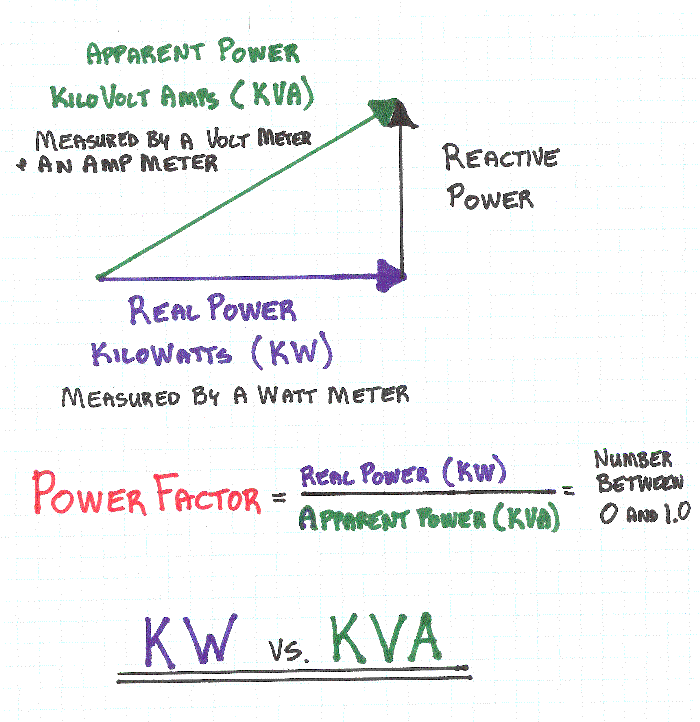
- Power factor in a single-phase circuit (or balanced three-phase circuit) can be measured with the wattmeter-ammeter-voltmeter method, where the power in watts is divided by the product of measured voltage and current. The power factor of a balanced polyphase circuit is the same as that of any phase. The power factor of an unbalanced polyphase circuit is not uniquely defined. A direct reading power factor meter can be made with a moving coil meter of the electrodynamic type, carrying two perpendicular coils on the moving part of the instrument. The field of the instrument is energized by the circuit current flow. The two moving coils, A and B, are connected in parallel with the circuit load. One coil, A, will be connected through a resistor and the second coil, B, through an inductor, so that the current in coil B is delayed with respect to current in A. At unity power factor, the current in A is in phase with the circuit current, and coil A provides maximum torque, driving the instrument pointer toward the 1.0 mark on the scale. At zero power factor, the current in coil B is in phase with circuit current, and coil B provides torque to drive the pointer towards 0. At intermediate values of power factor, the torques provided by the two coils add and the pointer takes up intermediate positions.[19] Another electromechanical instrument is the polarized-vane type.[20] In this instrument a stationary field coil produces a rotating magnetic field, just like a polyphase motor. The field coils are connected either directly to polyphase voltage sources or to a phase-shifting reactor if a single-phase application. A second stationary field coil, perpendicular to the voltage coils, carries a current proportional to current in one phase of the circuit. The moving system of the instrument consists of two vanes which are magnetized by the current coil. In operation the moving vanes take up a physical angle equivalent to the electrical angle between the voltage source and the current source. This type of instrument can be made to register for currents in both directions, giving a 4-quadrant display of power factor or phase angle. Digital instruments can be made that either directly measure the time lag between voltage and current waveforms and so calculate the power factor, or by measuring both true and apparent power in the circuit and calculating the quotient. The first method is only accurate if voltage and current are sinusoidal; loads such as rectifiers distort the waveforms from the sinusoidal shape.
Mnemonics
English-language power engineering students are advised to remember: "ELI the ICE man" or "ELI on ICE" – the voltage E leads the current I in an inductor L, the current leads the voltage in a capacitor C. Or CIVIL – in a capacitor(C) the current (I) leads voltage(V), voltage(V) leads current(I) in an inductor(L). See the Images below for further Information about


Tuesday, May 31, 2011
Measuring power factor
Subscribe to:
Post Comments (Atom)
No comments:
Post a Comment